Crouse Hinds Model KS Traffic Controller
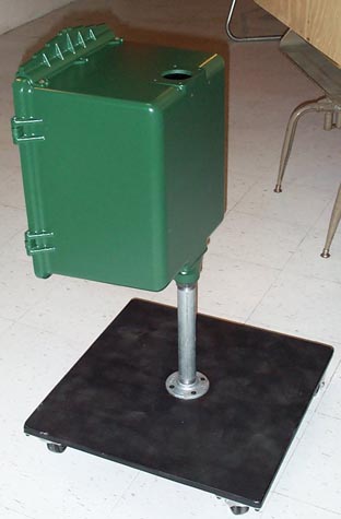
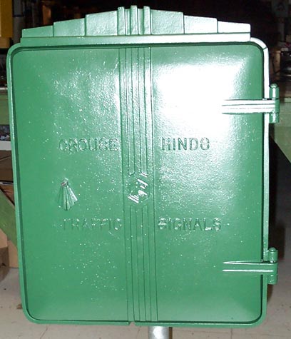
| This is the 4th controller added to this collection. It is a Crouse Hinds KS electromechanical controller. Definitely the oldest controller in this collection. It sports the same Art Deco decoration on the top of it as the Art Deco traffic signals from the same period, the 1940's and 50's. | |
|
|
|
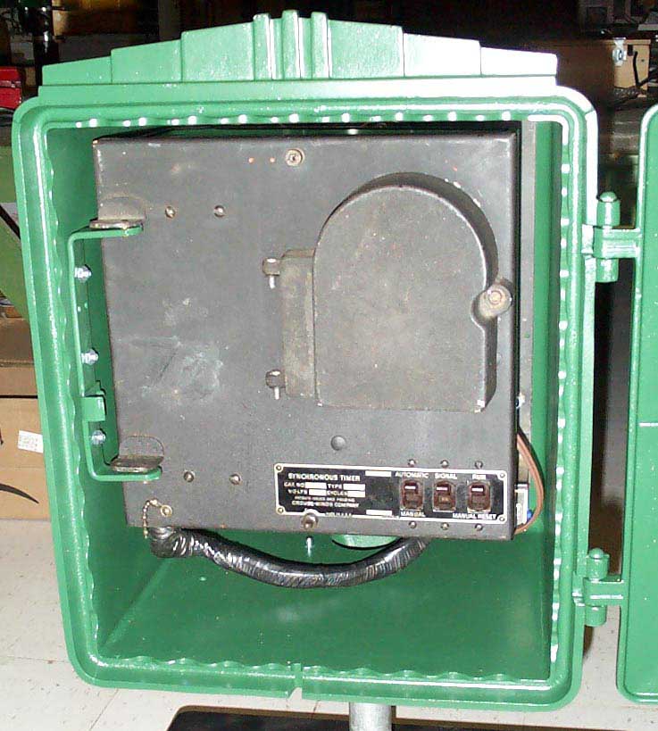
On the inside is the controller box. It has a single dial concealed by the small black door.
On the dial itself, there are 5 keys and below the dial are 3 contacts. One of the keys is labeled "I" for interlock. This keys function is to make sure the cam shaft and the dial stay in sync. When the cam shaft and dial are properly in sync, the "I" key always turns the main street green light to yellow. After that there are 3 other keys labeled "S". These keys are for the other three signal changes. Main street yellow to red with side street red changing to green. Then side street green changing to yellow and finally, side street yellow turning to red with main street red changing to green. If the dial and cam shaft were to get out of sync, the "S" keys would not advance the cam shaft once it reached the point that it needs the "I" key to advance and the dial will re-sync up once the "I" key comes around again. There are currently no cams in this controller for pedestrian signals. The controller was designed before the flashing DONT WALK phase was used, so this controller has room for 4 more cams. One for main street WAIT, one for main street WALK and one each for side street WAIT and WALK. This controller is capable of doing an all red intersection clearance phase if two more "S" keys were added and the cams were re-configured.
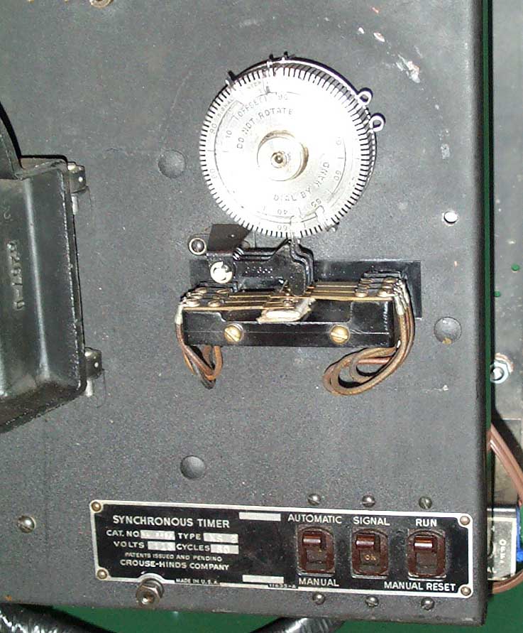
There is a fifth key on the dial labeled "R". This key is used in conjunction with the RUN/MANUAL RESET switch you see on the lower right corner of the controller in the above picture. These "synchronous timer" controllers were not capable of being interconnected with other controllers. But, they could be manually synced up using the manual reset switch. For example, if there were two of these controllers on a street and they were to be set up so that both sets of signals would change at the same time, flipping the reset switch down would allow the "R" key to stop the motor when it came around on the bottom of the dial. Both controllers would have to be geared and keyed so that they both had identical timing cycles. Then a person could go to one of the two controllers and flip the manual reset switch down so the controller stopped at the "R" key. By watching the other set of signals, the person could "release" the controller at the proper time and both controllers would then run identical cycles with the both sets of signals being red and green on the main street at the same time. As long as power is maintained to both controllers and both controllers remain in good operating condition, the controllers should stay in sync.
Below, the controller is swung out of the way to access the back panel. It is a very basic set up with outputs for two phase operation (main street and side street signals) of vehicle signals and pedestrian signals without the flashing DONT WALK indication.
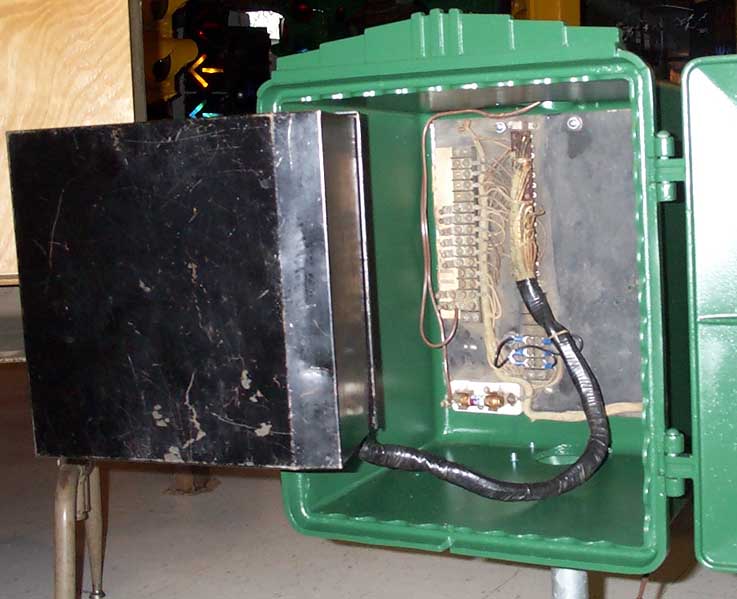
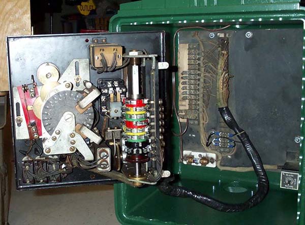
Although this controller is not set up for a time clock to put it in night time flash mode, it can be manually placed in flash with the toggle switch in the lower right corner on the back panel seen below. Also in the picture below the back cover of the controller is removed, exposing the "guts" of the controller.
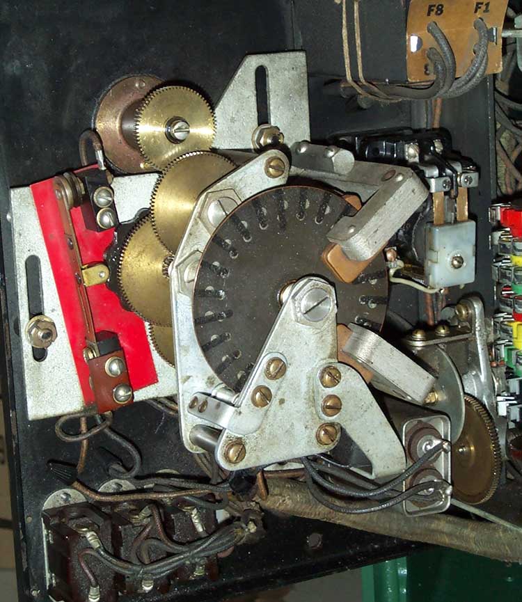
Here is a close up of the motor. It is powered by coils positioned over a magnetic copper disk so that the coils "attract" the disk and it rotates when power is applied. In the picture below, the disk appears to have many black lines on it. When running and viewed in a fluorescent or neon light source, the black lines will appear to stand still if the disk is turning at its proper running speed. If the lines appear to rotate either clockwise or counter-clockwise, the disk is running too fast or to slow and the coils will need to be adjusted to obtain the proper running speed again. For more technical information on this controller, click here. (Thanks to www.railroadsignaling.com for the info.) The upper most gear in the picture is interchangeable so the cycle length can be made longer or shorter. Mounted on the red area of the motor assembly is the flasher contact. This contact is pushed away and then allowed to come back and make contact again by the uneven round black disk to the right of the red area.
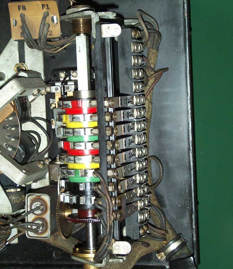
Below is a picture of the cam shaft and cam contacts. A smaller disk type motor is powered for a short time when the dial keys close the contacts on the front of the controller. This turns a couple of gears and rotates the cam shaft to change the signals. One thing about the cams in this controller unlike the Eagle controllers in this collection is that the cams can be re-configured. Eagle controller cams have to be broken out in the correct pattern and are not re-configurable. These cams have removable metal tabs and are completely re-usable and re-configurable! Where the metal tabs are removed from a cam, it allows the contact to make a connection and light up the signal. To see a short video of the motor and camshaft in operation, click here.
This page was originally posted on 8/3/2003.