Eagle Signal Model EF-15 Traffic Controller
This was the first real traffic controller in my collection. To see some video clips of an EF controller, go to the video clip page
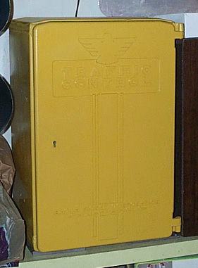
Here is a view of the front of the controller.
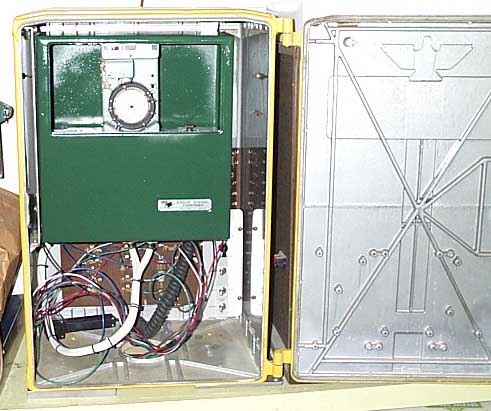
This picture shows the dial timer box on the inside of the controller.
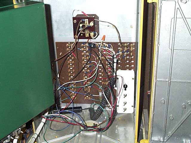
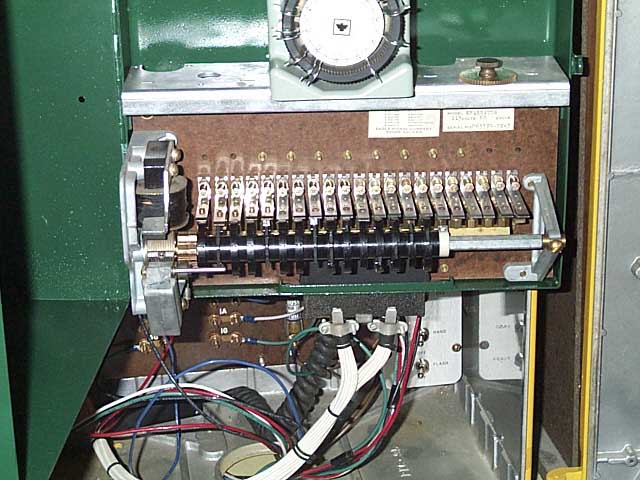
This is the back panel of the controller that all the signals are wired up to. The small square panel above the large panel is a single circuit flasher that I converted to a double circuit flasher that makes both of the pedestrian signal phases of the controller able to flash.
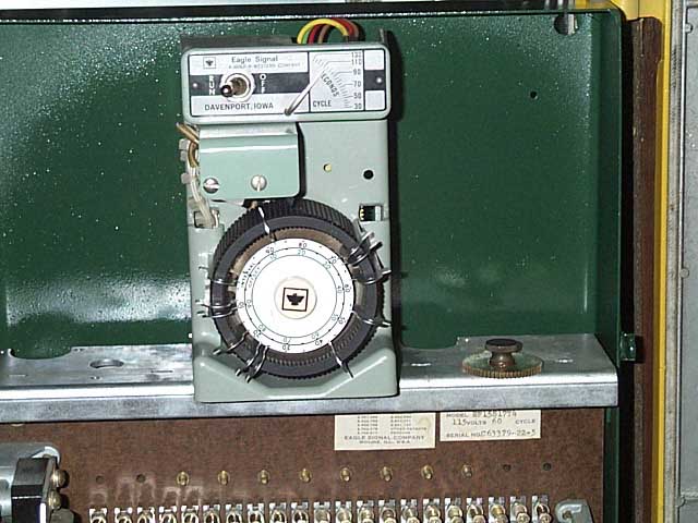
This is the dial timer. On the top, you can see a toggle switch on the left to turn off the timer while the signals still receive power from the back panel. To the right of the toggle switch is an indicator needle that points to how long the dial timer will take to make one complete revolution in seconds. This is controlled with an interchangeable gear on the inside of the timer. In this picture there is a 110 second gear installed. On the round black dial of the timer are keys that cause 2 electrical contacts to be closed each time one passes around the top of the dial. When the contacts are closed it energizes the cam shaft motor which is shown below.
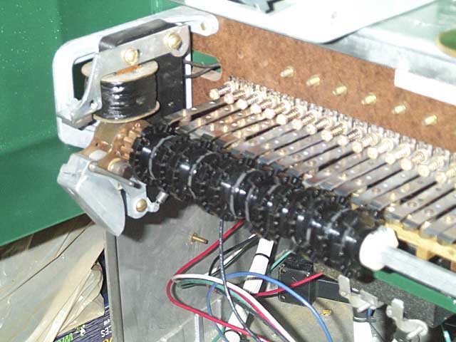
Here is a closer picture of the cam shaft and motor. The motor is on the left end of the shaft.
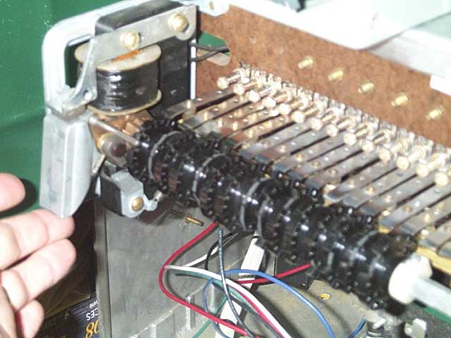
When the dial timer contacts are closed by the keys on the dial, and the cam shaft motor is energized, it lifts up into this position shown above. When the key on the timer dial passes the contact, the cam shaft motor power is cut and it drops back into it's lower position shown 2 pictures above. When it drops back, it causes the cam shaft to advance the cam dials to their next step and the fingers on the cam dials are lowered or raised causing the signals to advance to the next step in their cycle. By adding or removing cams and changing the way the cams are broken out, you can change how many signals this controller will handle and how they sequence.