Eagle Signal Model EF-70 Traffic Controller
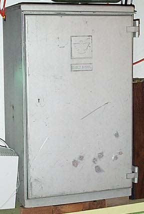 |
This is the third real traffic controller in my collection. It is quite heavy, and very cool to watch it in action. If you would like to download a short video clip of this controller in action,
click here.
The clip is just over 10 seconds in length. The file is just under 2.5 MB and may take around 15 minutes to download over a dialup connection.
There are more clips of this controller on the
video page.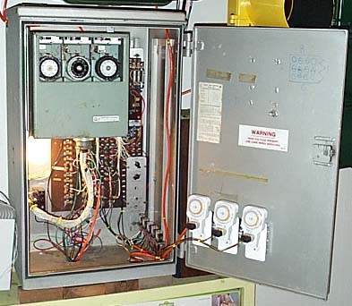 |
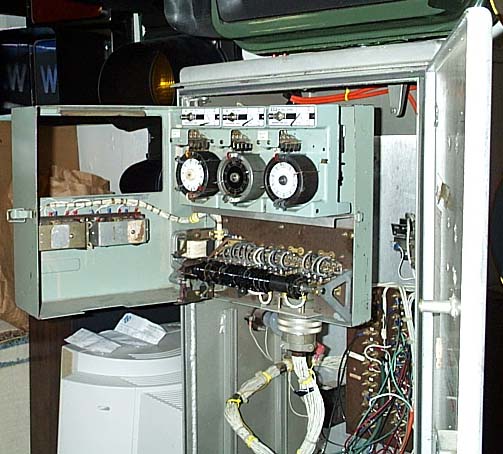
This picture shows the controller box on the inside of the cabinet. The controller box has three dial timers unlike the EF-15 controller that I own which only has one dial timer. Three dial timers allow for different signal timings for different times of day. I have set up dial one in this controller with a 40 second gear. This allows for very short green indications on both phases (directions). Then I installed keys on dial 1 that allow for coordination with other controllers. I have coordinated this dial timer with my NEMA controller. The R2 and R3 keys on dial 1 each are connected to their own relay which completes a circuit when there is a green light on my NEMA controller. When the circuit is completed, the R2 and R3 keys stop the dial 1 timer until the green light on the NEMA controller goes off, then the relay opens the connection and dial 1 starts up again. This keeps my EF-70 controller and my NEMA controller changing their signals within 1 second of each other. Dial 2 has a 70 second gear and does not have any coordination keys, so it runs independent of my NEMA controller and has a longer cycle. Dial 3 is also independent, but it has a 100 second gear for even longer cycles.
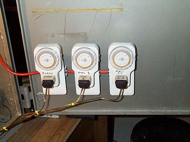
Above is a picture of three wall timers that I have wired to turn on and off three of the Double Pole Double Throw relays shown in the picture below. The first timer puts the controller in and out of flash mode. The second and third timers control which dial timer is on. The extra two relays below are used with the coordination keys that I mentioned above.
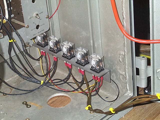
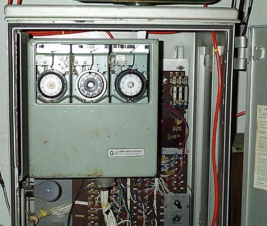
Besides the timers on the doors and the relays shown in the picture above, there are two relays inside the door of the controller box that do the actual switching of dial timers. They are called dial transfer relays. The cam shaft of the controller is set up so that dial switching only occurs when main street green comes around on the cam shaft. Then, depending on the state of the Double Pole Double Throw relays controlled by the wall timers, the dial transfer relays switch to whatever dial is being called for at that time. Dial timers can also be manually selected by the rotary switch on the back panel. If a dial is called for on the rotary switch, this dial will remain active until the rotary switch is set to a different dial. For the timers to select dial timers automatically, the rotary switch must be set to CL which stands for CLOCK. The dial transfer relays are shown below just below the window in the controller box door.
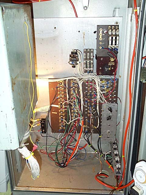
Below is the back panel of the controller that all the signals are wired up to. There are also two flash transfer relays, a flasher which flashes the pedestrian signals in normal mode and the yellow and red signals in night flash mode. Also included on the back panel is a mercury relay which cuts power to the signals in flash mode.
For more details on how the cam shaft and dial timers turn the signal indications on and off,
please see my EF-15 controller page.
This page was originally posted on 3/2/2003.